Why Dropping Your MacPherson Struts Ruins Cornering Grip (and How to Fix the Kinematics)
The Low Stance Trap and the Reality of MacPherson Geometry
Lowering a car is often treated as a guaranteed handling upgrade. The visual change is immediate, and a reduced centre of gravity can sound like an automatic route to sharper turn-in, less body roll and faster lap times. In practice, ride height is only one part of the suspension equation. On a MacPherson strut platform, lowering beyond the range intended by the original designers can move the suspension into a geometrically inferior operating position, even when the car looks more purposeful.
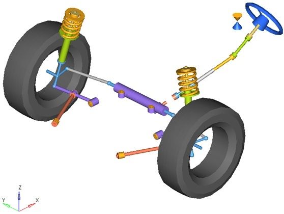
This matters particularly to drivers chasing measurable front-end grip rather than stance alone. Unlike a double-wishbone system, a MacPherson strut uses the damper and upright as a major locating member, with the upper strut mount serving as a high pivot and the lower control arm defining much of the wheel”s lateral movement. Once the control arm angles upwards from the chassis towards the wheel, the kinematic relationships change rapidly. Roll-centre height falls, camber recovery worsens and toe can become unstable. The result is a car that may feel firm and aggressive in the paddock but gives away confidence, contact patch and speed in a loaded corner.
How Slamming Your Car Destroys the Instant Centre and Roll Centre
The instantaneous centre is a geometric point used to describe the momentary centre of rotation of a suspension assembly. On a simplified MacPherson strut, the lower control arm is extended geometrically until it intersects the projected line of the strut. That intersection forms the instant centre for the wheel”s lateral movement. The relationship between the left and right instant centres, together with the tyre contact patches, establishes the axle”s kinematic roll centre. It is not a physical component that can be touched or adjusted directly, but a calculated point that changes every time the suspension moves.
The roll centre determines how lateral forces are divided between geometric load transfer through the suspension links and elastic load transfer through the springs, dampers and anti-roll bars. A higher roll centre can reduce the roll moment arm between the vehicle”s centre of gravity and the roll centre, but excessive height can introduce jacking forces and harsher load paths. A sensible explanation of this relationship is provided in Racecar Engineering”s roll centre guide, which also stresses that roll centre must be considered alongside compliance, migration and tyre behaviour.
At standard ride height, the lower arm usually operates with a controlled downward angle from the inner chassis pivot to the outer ball joint. Lower the car substantially and that angle reduces until the arm becomes horizontal, then reverses. Once the outer ball joint sits higher than the inner pivot, the projected instant centre moves dramatically. The roll centre can migrate towards the centreline, move laterally in a corner and, on some layouts, fall below the road surface.
- The lower arm passes through horizontal and begins pointing upwards towards the wheel.
- The instant centre moves a long distance or changes rapidly with small suspension movements.
- The kinematic roll centre may fall below ground level.
- The distance between the centre of gravity and roll centre increases, increasing the roll moment lever arm.
- Roll, camber change and load transfer become more sensitive to bump and roll position.
A sub-ground roll centre does not mean the car cannot corner, but it means the springs and anti-roll bars must resist a much larger roll moment. More importantly, the suspension may exhibit poor roll-centre migration and undesirable lateral wheel movement. Increasing spring rate can limit visible body movement, yet it cannot restore the lost geometry. This is why understanding lateral load transfer requires evaluating the instantaneous roll centre and its relationship to the centre of gravity, rather than judging the car by ride height or static roll alone.
Dynamic Camber Loss and the Disappearing Tyre Contact Patch
MacPherson struts have an inherent camber limitation because the upper strut mount and lower ball joint define the wheel”s steering and suspension axis. As the outside wheel compresses in a corner, the wheel needs to gain sufficient negative camber to remain square to the road. If the geometry instead produces positive camber gain, or simply fails to recover the camber lost through body roll, the tyre leans onto its outer shoulder. The contact patch becomes narrower and less evenly loaded, reducing braking stability, turn-in authority and mid-corner grip.
Adding static negative camber can compensate for part of this problem, but it is not a complete solution. Static alignment is measured with the car stationary and the suspension at a chosen ride height. Dynamic camber is the angle the wheel actually achieves as the body rolls, the outside suspension compresses and the inside suspension extends. A heavily lowered car may require an aggressive static setting merely to produce an acceptable loaded angle, creating inner-edge wear on the road and still failing to maintain the correct contact patch at the circuit.
The strut inclination angle also changes the leverage and movement of the upright. When the lower arm points upwards, the wheel can move laterally in an undesirable direction through bump, while the roll centre falls and body roll increases. The result is often misdiagnosed as a need for harder springs or a larger anti-roll bar. A more useful comparison is to inspect the complete kinematic curve rather than one static alignment figure.
| Ride-height condition | Typical geometric behaviour | Likely driving result |
|---|---|---|
| OEM or modestly lowered | Control arm retains a useful downward angle, with predictable roll-centre movement and manageable camber change. | Consistent contact patch, stable steering and broad usable grip. |
| Slammed without correction | Control arm passes horizontal, roll centre drops and camber recovery becomes less favourable through compression. | Outer-shoulder loading, vague mid-corner response and increased dependence on stiff springs. |
| Lowered with corrected geometry | Ball-joint and upright relationships are restored, while camber and roll-centre curves are brought closer to a useful operating range. | Improved front-end bite, more predictable load transfer and better tyre consistency. |
On platforms such as the A90 Supra, a professional alignment, suitable camber and caster adjustment, firmer control-arm bushes and correctly chosen dampers can improve front grip and steering response, as outlined in this Supra suspension upgrade guide. The critical point is sequencing. Alignment and geometry must be established before judging spring rates, damping or anti-roll-bar settings.
The Secondary Menace of Severe Bump Steer and Toe Instability
Bump steer is steering movement created by suspension travel rather than by the driver turning the steering wheel. The lower control arm and the steering tie rod each follow an arc around their respective pivots. At the intended ride height, those arcs are designed to remain reasonably synchronised. Lower the car beyond that range and the tie-rod angle may no longer match the control-arm angle, causing the wheel to toe in or toe out as it moves through bump and rebound.
During a fast corner, the outside front wheel is compressed by both road inputs and lateral load transfer. If that wheel suddenly gains toe-out, the driver may feel a sharp increase in steering response followed by instability or snap understeer. Excessive toe-in can create a delayed, resistant turn-in followed by a sudden change as the suspension passes through a different part of its arc. The effect is especially unpleasant over kerbs, compressions and uneven braking zones because the steering angle changes without a corresponding driver input.
Production-based modified cars are particularly vulnerable because the original chassis pickup points are fixed. The MotoIQ bump-steer explanation identifies excessive lowering as a common cause and notes that keeping a drop within roughly one or two inches often avoids the worst geometry changes. That is a useful rule of thumb, not a substitute for measurement, because different platforms have different control-arm lengths, steering racks and intended travel.
- Do not assess bump steer from the steering wheel alone. Measure toe at several points through bump and rebound.
- Check the outside front wheel”s toe change across the loaded portion of its travel.
- Inspect rack position, tie-rod angle and clearance before selecting correction parts.
- Do not use extreme spring rates to hide steering movement caused by poor toe curves.
High spring rates can mask the symptom by reducing the amount of suspension travel, but they do not correct the arc mismatch. The car may feel calmer on a smooth circuit while becoming harsher, less compliant and more unpredictable over kerbs. A wheel that cannot follow the road is not generating reliable grip. Geometry correction should come first, followed by spring and damper selection based on the remaining roll, heave and tyre requirements.
Proven Engineering Solutions to Restore Proper MacPherson Kinematics
The correct repair depends on how far the car has been lowered and how much adjustment the original platform provides. For a mildly lowered fast-road car, extended ball-joint pins or dedicated roll-centre correction plates can reposition the outer control-arm pivot lower relative to the upright. This restores a useful downward control-arm angle and moves the roll centre back towards a sensible height. The parts must be designed for the specific upright and ball-joint taper, with adequate articulation, thread engagement and clearance at full lock and full bump.
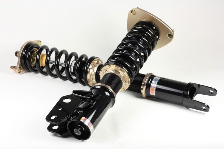
More extreme track builds may require a drop knuckle or a revised upright with the spindle relocated relative to the hub carrier. This approach can preserve lower ride height while restoring suspension travel and improving the relationship between the ball joint, strut and steering arm. It is a more comprehensive solution than simply adding a spacer, but it demands careful checks for driveshaft angle, brake-disc position, wheel clearance, steering-arm strength and compliance with competition regulations.
Tie-rod correction must be treated as a separate part of the job. A corrected control-arm angle can leave the steering linkage misaligned if the rack and steering arm remain in their lowered-car position. Adjustable tie-rod ends, shims where appropriate, or inverted spherical joints can alter the outer steering pivot height and bring the tie-rod arc back into phase with the control arm. Every solution needs a bump-steer check, because visual alignment of the two parts is not proof that the toe curve is correct.
- Record the baseline. Measure ride height, corner weights if available, static camber, caster and toe. Remove springs or use a suitable suspension rig to record toe and camber at defined bump and rebound positions.
- Correct the primary suspension geometry. Restore the lower control arm to a useful downward operating angle with an approved ball-joint extension, correction plate, drop knuckle or revised upright. Check travel, ball-joint articulation and all mechanical clearances.
- Correct steering geometry. Adjust the tie-rod outer pivot, rack position or steering arm as required. Re-measure toe through travel, paying close attention to the compression range used by the outside front tyre in a corner.
- Align and validate on track. Set camber, caster and toe only after the geometry is corrected. Confirm tyre temperatures, shoulder wear, steering feel and lap consistency, then make one change at a time.
For road and track use, the final setup must retain adequate bump travel and avoid relying on bump stops as a secondary spring. Inspect bushes, top mounts, wheel bearings and subframe fasteners before interpreting handling data. Adjustable camber plates and solid or firmer control-arm bushes can improve consistency, but they also transmit more noise and vibration. The best result is not the lowest possible car. It is the lowest height that preserves usable travel, stable toe, sensible camber recovery and predictable tyre loading.
Reclaim True Front-End Bite Through Measured Geometry
Aesthetic ride height and functional ride height are not the same thing. Dropping a MacPherson strut platform until the lower control arm points upwards can increase the roll moment lever arm, degrade camber behaviour and introduce severe bump steer. Stiffer springs may reduce the visual symptoms, and more negative static camber may improve one corner of the setup sheet, but neither restores the kinematic relationships that control the contact patch.
The reliable route to faster lap times is measurement. Check the control-arm angle, calculate or measure roll-centre movement, record dynamic camber and map toe through the actual suspension travel used on track. Correct the pivot locations first, then tune springs, dampers, anti-roll bars and alignment around the restored geometry. A car that sits slightly higher but keeps its tyres square, its steering predictable and its suspension compliant will usually deliver greater confidence, stronger front-end bite and more repeatable circuit pace than a car built purely for a low visual line.