Before the Dyno: Mechanical Health Checks for High-Mileage Turbo Petrols
Why High-Mileage Turbo Petrols Fail Under Dyno Load
A rolling-road session is far more demanding than ordinary road use. On the street, a turbocharged petrol engine usually experiences changing load, airflow, throttle position and engine speed. A chassis dynamometer can hold the engine at a heavy, sustained load while the operator completes repeated power runs. That combination produces prolonged cylinder pressure, exhaust heat, turbocharger speed and under-bonnet temperature, often while the vehicle is stationary and dependent on the dyno cell”s cooling fans.
High mileage magnifies every weakness. Piston rings may no longer seal as effectively, valve seats can lose their margin, coolant hoses and plastic fittings become brittle, and a water pump impeller may have eroded or slipped on its shaft. Boost hoses harden, intercooler end-tanks fatigue and diverter valves lose sealing force. None of these faults necessarily prevents a car from commuting, but a dyno run exposes them quickly. The correct engineering mindset is therefore simple: validate the engine before asking the calibration to make more power. A modest diagnostic bill is considerably cheaper than a lifted head, damaged turbocharger or failed bottom end.
Static and Dynamic Compression Testing Benchmarks
Compression testing is one of the fastest ways to establish whether an older turbo petrol engine has a sound combustion foundation. With the engine at a suitable temperature, the ignition and fuel systems safely disabled, and the throttle held open, each cylinder can be tested using the same gauge and the same cranking procedure. Absolute figures vary between engines, compression ratios, camshaft profiles and test equipment, so the relationship between cylinders is often more useful than a single headline number. As a practical workshop benchmark, aim for less than a 10 per cent difference between the highest and lowest cylinder, while also comparing the result with the manufacturer”s specification.
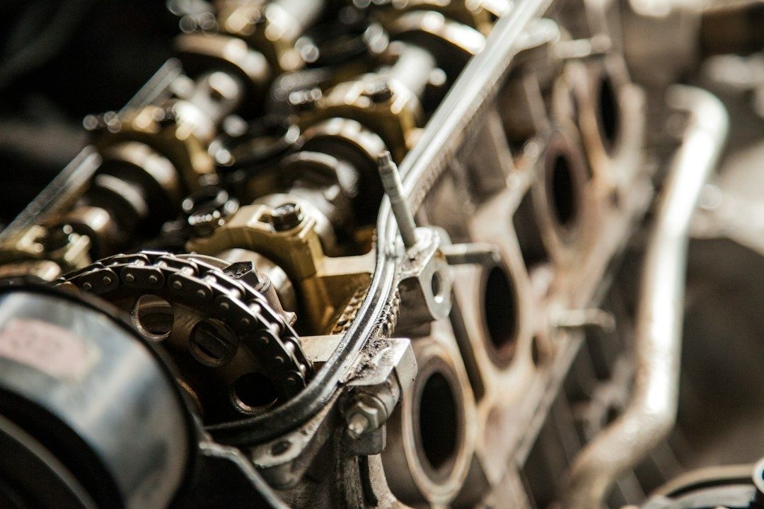
A dry test records the pressure produced with the engine in its normal condition. If one cylinder is low, a small quantity of clean engine oil can be added and the test repeated as a wet comparison. A significant improvement points towards ring or bore sealing, because the oil temporarily helps close the gap between the piston rings and cylinder wall. Little or no improvement directs attention towards a valve seat, valve face, head gasket or, on some engines, a cam timing issue. A leakdown test adds greater precision by feeding regulated compressed air into each cylinder at a defined piston position. Air heard at the crankcase suggests ring leakage, noise at the intake suggests an inlet valve problem, and noise at the exhaust points towards an exhaust valve fault.
These checks matter even more before an aggressive remap. Increased boost and ignition advance raise cylinder pressure, while richer or leaner mixtures and altered torque targets can expose a marginal seal that survived standard calibration. Combustion leakage can also increase crankcase pressure, oil consumption and intake contamination. Understanding combustion health supports successful engine tuning and helps preserve longevity on the rolling road.
| Test result | Likely interpretation | Dyno decision |
|---|---|---|
| Even compression, less than 10 per cent spread | Healthy baseline, subject to leakdown and oil-consumption checks | Proceed with normal supporting inspections |
| Low cylinder that improves substantially when wet | Possible ring, bore or piston sealing issue | Investigate before applying additional boost |
| Low cylinder with little wet-test improvement | Possible valve, seat, head gasket or timing fault | Do not tune until diagnosed |
| Adjacent low cylinders | Possible head gasket or localised head problem | Stop and confirm with leakdown and cooling-system checks |
Crankcase Pressure and Positive Crankcase Ventilation Integrity
Blow-by is unavoidable in a piston engine, but excessive blow-by becomes a serious concern when boost increases. Combustion gases passing the rings pressurise the crankcase, and a restricted or incorrectly functioning positive crankcase ventilation system may be unable to remove them. Typical warning signs include oil pushed from seals, fresh wetness around the rocker cover, smoke after extended boost, oil pooling in charge pipes and a dipstick that lifts or ejects under load. A vehicle can still produce apparently respectable power while the crankcase ventilation system is approaching failure.
Inspect the PCV valve, one-way check valves, hoses, baffles and oil separator for blockage, diaphragm damage and incorrect routing. Check valves must allow flow in the intended direction and prevent boost from entering components designed to operate under vacuum. A separator should remove oil mist without imposing excessive restriction. During diagnosis, measure crankcase pressure with a suitable gauge or manometer under idle and loaded conditions rather than relying only on a finger placed over the filler cap.
- Confirm that every PCV hose is intact, correctly connected and free from sludge.
- Test one-way valves for both flow direction and positive sealing.
- Inspect the oil separator or catch-can system for saturation and restriction.
- Look for oil residue at turbocharger compressor seals, intercooler joints and breather connections.
- Investigate any dipstick movement, seal leakage or sudden increase in oil consumption.
Excess crankcase pressure can force oil past turbocharger sealing arrangements, although smoke from the exhaust should not automatically be blamed on the turbo. It can also overwhelm gaskets and seals, contaminate the charge tract and reduce the consistency of dyno readings. PCV hardware is inexpensive compared with an engine rebuild, making it a non-negotiable inspection on a high-mileage performance car.
Forced Induction Smoke Testing and Charge Pipe Verification
A boost leak is not merely a nuisance that costs a few pounds of torque. On a turbocharged engine, an air leak changes the relationship between measured airflow, throttle position, manifold pressure and turbocharger speed. The engine management system may respond by commanding more compressor work to achieve its target pressure, while the escaping air prevents that target from being reached efficiently. The result can be slow spool, unstable boost, poor fuelling control and excessive turbocharger speed.
Pressure testing should be performed with the engine off and with suitable plugs installed at the turbocharger inlet or charge-system connection, depending on the engine layout. Do not blindly apply the vehicle”s maximum boost pressure to a system containing components that were not designed for static pressure. Use a regulated air source, a calibrated gauge and soapy water or a smoke machine to locate escaping air. The test pressure should be chosen sensibly for the specific engine and should remain below the safe limit of the weakest component.
- Remove the intake or charge connection needed to isolate the pressurised tract.
- Fit a properly sealed test adaptor and connect a regulated air supply with a gauge.
- Raise pressure gradually, listening for leaks and monitoring whether the system holds steady.
- Apply soapy water or smoke around couplers, clamps, welds, end-tanks and valve bodies.
- Repair the fault, repeat the test and confirm that the system remains stable before road or dyno operation.
Common failure points include silicone couplers that have softened with oil exposure, clamps positioned behind rather than over the bead of a pipe, intercooler end-tank crimps, throttle-body seals and diverter or blow-off valves. Vacuum-operated actuators and boost-control solenoids should also be checked for correct hose routing. A smoke test is particularly useful for small leaks that may not produce an obvious hiss at modest pressure.
Unmetered air escaping after the mass-airflow sensor can create a closed-loop overspeed cycle. The turbo works harder to replace lost charge air, the control system requests more duty or load, and the compressor operates further towards an inefficient part of its map. Charge temperature rises, the leak worsens as couplers move under torque reaction, and the final dyno pull can become far more stressful than the numbers suggest. Sealing the tract first gives the calibrator a stable platform and protects the turbocharger from unnecessary work.
Thermal Envelope and Cooling System Preparedness
Cooling-system condition must be judged under sustained load, not merely by whether the temperature gauge sits in its usual position during a short drive. Test coolant level and mixture with the engine cold, inspect the radiator, expansion tank, hoses and pressure cap, and confirm that the electric fan operates at the required temperatures. An aged water pump may have a damaged, slipping or corroded impeller, reducing flow precisely when the engine needs it most. A thermostat that opens slowly or fails to open fully can create a misleading pattern of normal cruising temperature followed by rapid heat rise during a power run.
A stationary dyno session is a severe heat-soak test. Even a large fan cannot perfectly reproduce the pressure distribution and under-bonnet evacuation created by a moving vehicle. The radiator must reject heat while the intercooler, exhaust manifold, turbocharger and engine block are all contributing to the thermal load. Monitor coolant temperature, oil temperature, intake-air temperature and, where available, exhaust gas temperature or knock activity. Stop the session if temperatures trend away from control rather than waiting for a warning lamp.
- Verify thermostat opening behaviour and stable coolant temperature.
- Check water-pump condition, belt drive and evidence of coolant circulation.
- Inspect radiator fins for blockage, corrosion and collapsed sections.
- Confirm correct fan operation, shrouding and airflow direction.
- Use suitable high-temperature engine oil with a known service history.
- Check coolant concentration and use a specification-approved mixture.
- Inspect brake fluid age and boiling-point specification before repeated dyno braking or track use.
Fluids deserve the same discipline as hardware. Old oil may have lost viscosity control and oxidation resistance, while contaminated coolant can promote corrosion and reduce reliable heat transfer. Brake fluid is not part of the engine calibration, but a dyno cell session can be followed immediately by track work, and aged fluid has little margin when temperatures rise. Fresh, correctly specified fluids remove variables and make any subsequent performance diagnosis more meaningful.
Ensuring Peak Reliability on the Dyno Rollers
Safe power extraction starts with mechanical integrity, not the map file. A dyno operator can control load, monitor data and stop a run, but no operator can compensate for a cracked charge pipe, a failing water pump or a cylinder that is already losing sealing pressure. The most reliable approach is to treat the pre-dyno inspection as a pass or fail engineering audit rather than an optional service.
Before signing the dyno paperwork, confirm that the engine has an even compression pattern, no unexplained leakdown loss, controlled crankcase pressure and a charge system that holds its test pressure. The cooling system should maintain stable temperatures under controlled load, oil and coolant levels should be correct, and all ignition, fuelling and boost-control components should be free from known faults. Any unresolved warning light, misfire, oil-pressure concern or abnormal smoke is a reason to postpone tuning.
- Record compression results for every cylinder and investigate any spread approaching 10 per cent.
- Complete a leakdown test where compression results, oil use or blow-by are questionable.
- Verify PCV flow, check-valve sealing and crankcase pressure.
- Pressure-test or smoke-test the full charge-air tract and repeat the test after repairs.
- Confirm coolant circulation, thermostat response, fan operation and radiator condition.
- Fit serviceable oil, coolant and brake fluid with the correct specifications.
- Inspect belts, hoses, clamps, tyres, wheel fixings and fluids immediately before strapping the car down.
- Agree monitoring limits and an emergency stop procedure with the dyno operator.
That checklist does not guarantee a particular power figure, because fuel quality, ambient temperature, engine condition and calibration strategy still matter. It does, however, remove many of the avoidable failure modes that turn an exciting tuning session into an expensive recovery. A high-mileage turbo petrol can deliver dependable performance, but only when the dyno is used to measure a healthy engine rather than to discover its weaknesses.