Bar-and-Plate vs Tube-and-Fin: Sizing Intercooler Cores for Fast Road Response
The Real Trade-Off Between Intake Density and Boost Threshold
For a fast-road turbocharged car, fitting the largest intercooler that will physically fit is rarely the complete answer. A large matrix can provide impressive temperature control during a long dyno pull, yet still compromise the sharper response that makes a car enjoyable on a technical UK B-road. The correct choice is an engineering compromise between charge-air cooling, pressure drop, internal volume, packaging and the engine”s actual duty cycle. A well-matched performance intercooler core should support the target airflow without creating unnecessary work for the turbocharger.
Charge volume matters because every change in throttle position or gear requires the turbocharger to pressurise the air path between the compressor and inlet valves. Increasing the core and plenum volume can add a small amount of transient delay, particularly on a modestly sized turbo operating at relatively low engine speed. Internal friction has a similar effect. A restrictive core creates a pressure difference that the compressor must overcome before the engine receives the intended manifold pressure. On a technical road, where the throttle is repeatedly opened, lifted and reapplied, recovery speed can matter more than the peak temperature recorded during one full-throttle dyno run. Thermal inertia, heat rejection during off-boost cruising and consistent ECU control are central to usable performance.
Structural Anatomy of Bar and Plate Versus Tube and Fin Cores
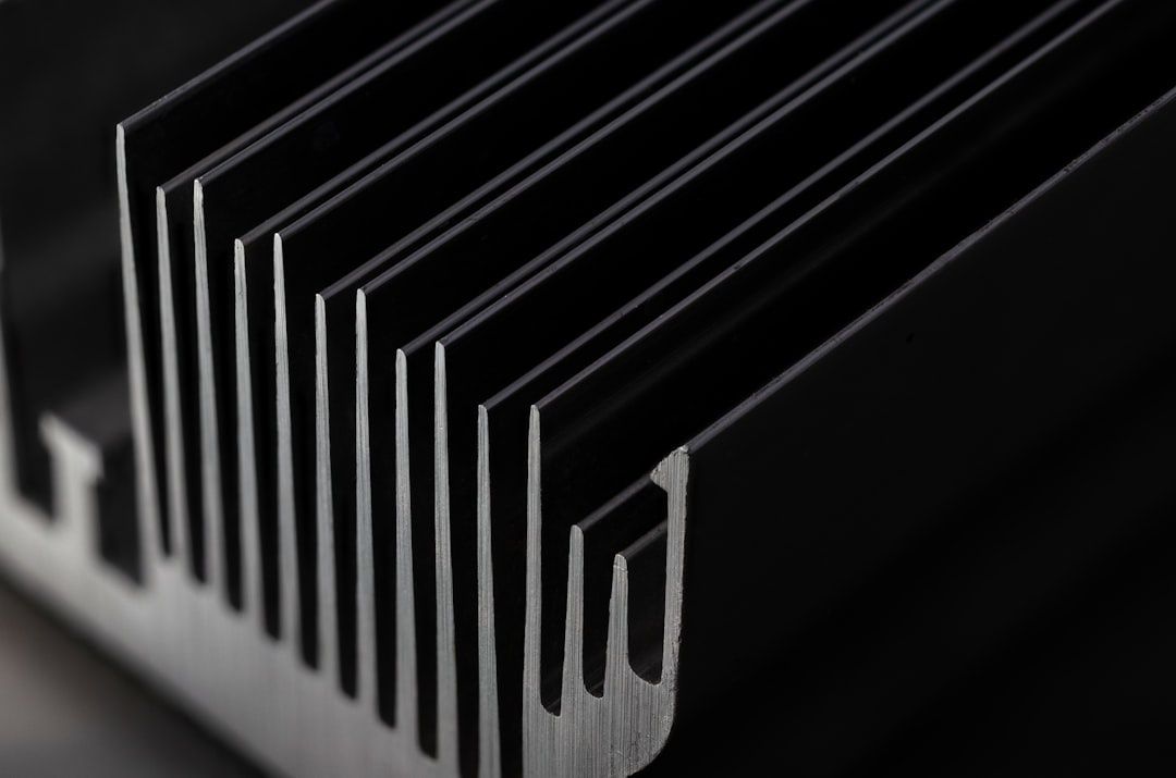
Bar-and-plate intercoolers are built from stacked plates, bars, internal fins and side plates. The construction is mechanically robust, with substantial material surrounding the charge-air passages. That mass provides a useful heat sink when the engine is subjected to repeated high-load operation, and it tolerates high boost pressure and vibration well. The internal passages can be configured to control flow distribution, while fin density is normally selected to balance heat transfer against restriction. Garrett describes heat removal as a combination of conduction through the core material and convection into the ambient airflow, with passage design playing a major role in the final result.
Tube-and-fin cores use lighter extruded tubes with fins attached between the charge-air passages. Their walls are generally thinner, and the overall assembly contains less metal than a comparable bar-and-plate unit. This reduces weight and often reduces the amount of retained heat after a high-load event. The trade-off is lower structural reserve in some designs, particularly where very high boost, aggressive fabrication or repeated motorsport abuse is expected. Tube-and-fin construction can also offer useful airflow characteristics through the core, although the exact result depends on tube shape, fin density, frontal area and the quality of the end tanks.
| Characteristic | Bar and plate | Tube and fin |
|---|---|---|
| Thermal mass | Higher, useful during sustained load | Lower, allowing quicker heat release |
| Weight | Usually heavier | Usually lighter |
| Pressure capability | Generally very strong | Dependent on tube and tank design |
| Transient behaviour | Can carry greater internal volume | Often suited to responsive fast-road systems |
| Best application | High boost, track and repeated sustained load | Road cars, compact packaging and lower mass |
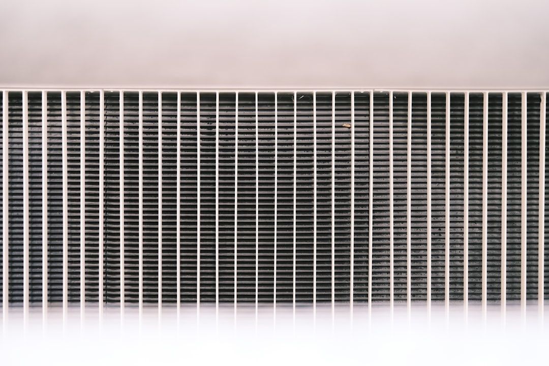
Frontal restriction is just as important as charge-air cooling. A deep, tightly packed bar-and-plate matrix may cool efficiently but can obstruct airflow reaching the engine coolant radiator, air-conditioning condenser and oil cooler. That effect becomes significant on a warm day or during a track session, when coolant temperature is already elevated. A lighter tube-and-fin core with suitable frontal area may offer adequate charge cooling while allowing more air to reach the primary radiator. The intercooler should therefore be judged as part of the complete cooling stack, not as an isolated component.
Weight and position also influence the car. A large bar-and-plate intercooler mounted ahead of the front axle adds mass at the worst possible height and location for turn-in response. The change may be modest on paper, but front-end weight affects steering effort, suspension response and the load carried by the front tyres under braking. For a road car that also sees track use, the best installation is normally the smallest core that meets the measured airflow and temperature requirement, positioned with short pipework and properly supported brackets.
Pressure Drop and Internal Volume Dynamics on Technical UK B-Roads
Internal volume is often discussed as if it directly creates turbo lag, but the more accurate explanation is that additional volume increases the amount of air that must be pressurised during a transient event. The effect depends on turbocharger flow, wastegate control, throttle strategy, pipe diameter and the pressure ratio across the system. A large core will not automatically make a car sluggish, particularly when its internal passages are efficient. However, an oversized core combined with long pipework and large end tanks can make boost recovery feel softer between gear changes.
Pressure drop creates a different penalty. If the engine requires a specific manifold pressure and the intercooler loses 2 psi across the matrix, the compressor must generate that extra pressure upstream. This raises compressor pressure ratio, shaft speed and discharge temperature, depending on the turbocharger operating point. A commonly discussed example involves a turbo producing 11 psi at the manifold while losing 3 psi through the intercooler. Restoring 11 psi after the core means the compressor may need to produce approximately 14 psi before the loss, although the exact pressure ratio must account for absolute pressure rather than gauge pressure. The practical implication is clear: measuring only boost at the inlet manifold can hide an inefficient or restrictive intercooler system.
Pressure loss must be evaluated alongside charge temperature. A core that produces slightly lower outlet temperature but imposes a large pressure penalty may not improve overall engine efficiency. Conversely, the lowest-restriction design is not automatically best if its cooling performance collapses after heat soak. During rapid on-off throttle driving, a useful system should recover pressure quickly, maintain stable outlet temperatures and avoid pushing the turbocharger towards an inefficient part of its map.
- Measure pressure before and after the intercooler at the same engine speed and load.
- Compare intake temperature at the compressor outlet, intercooler outlet and manifold.
- Assess boost recovery after each gear change, not only peak boost on a single pull.
- Check whether the turbocharger is operating at a higher pressure ratio simply to compensate for core restriction.
- Inspect end-tank shape and pipe transitions, because poor entry design can create more loss than the matrix itself.
Rough sizing rules can be useful as a starting point, but they are not substitutes for measurement. An enthusiast discussion regarding a 220 bhp diesel application used approximately three litres of core volume and 50 square centimetres of cross-sectional area per 100 bhp. That produced an indicative requirement of about 6.6 litres and 110 square centimetres for the target. Such rules can narrow the options, but they do not fully account for boost pressure, turbocharger efficiency, pipe length, engine speed or ambient temperature. Treat the figures as a screening tool rather than a guaranteed performance formula.
Thermal Inertia Versus Fast Recovery for Repeated Full Throttle Pulls
A heavy bar-and-plate core can resist an initial temperature rise because its metal mass absorbs heat from the charge air. This is valuable during sustained boost, especially on track where the throttle may remain open for long periods. The same thermal inertia can become a disadvantage after the car has heat-soaked. Once the core and surrounding front-end components are hot, the unit may take longer to shed retained energy, particularly if the car returns to the pits or spends time in slow traffic with limited airflow.
A lightweight tube-and-fin core generally reaches operating temperature quickly but can also release heat quickly when the vehicle returns to off-boost cruising. That behaviour often suits a fast-road car, where full-load events are brief and separated by braking zones, junctions and moderate-load sections. Elevated intake temperature affects more than power output. Engine management systems use intake temperature to estimate air density and calculate fuel delivery. Removing or ignoring that correction can create incorrect fuelling when ambient conditions genuinely change. The technical discussion around intake temperature correction correctly highlights that heat soak should be solved mechanically and through sensible sensor placement, rather than hidden by disabling density compensation. Ignition timing may also be reduced by the ECU when charge temperatures rise, protecting the engine but reducing torque.
Practical Core Sizing Calculations for Fast Road and Track Applications
Start with the engine”s realistic airflow requirement rather than an aspirational dyno figure. Brake horsepower, fuel type, volumetric efficiency, engine speed and boost level all influence mass airflow. A petrol turbo engine may require roughly 0.45 to 0.55 pounds of air per hour for each horsepower at full load, depending on its brake-specific fuel consumption and calibration. A 300 bhp target therefore implies approximately 135 to 165 pounds of air per hour, or around 0.017 to 0.021 kilograms per second. This is only an estimate, but it gives a more meaningful design basis than choosing a core because its dimensions look impressive.
Core volume should then be considered with the complete pipe system. A compact engine bay with short charge pipes may perform better with a modest-volume core than a larger unit connected by long, oversized plumbing. Face area is also important because greater frontal area can support airflow with lower velocity through the matrix. Core thickness should not be increased automatically, since a deep core can restrict the radiator stack and may receive less effective airflow behind the front bumper.
- Determine realistic airflow. Use the intended power level, engine speed and turbocharger data to estimate mass airflow. Include a margin for future development, but avoid sizing around an unlikely maximum figure.
- Target sensible pressure loss. Aim to keep the measured drop across the core and tanks within approximately 1.0 to 1.5 psi at the intended maximum airflow, while recognising that the acceptable value depends on turbo size and operating pressure. Compare pressure before and after the intercooler, not just manifold boost.
- Protect the cooling package. Confirm that the chosen core leaves sufficient open area for the coolant radiator, oil cooler and condenser. Use ducting and sealing so air passes through the matrix rather than escaping around it.
- Check the installation dynamically. Log intake temperature, coolant temperature, boost, throttle position and ignition correction during repeated road or track pulls. A core that looks excellent on one dyno run may perform poorly after several laps.
Packaging should also include service access and mechanical support. Silicone couplers need proper bead-rolls and clamps, while brackets must prevent the intercooler from hanging from the plastic bumper or aluminium charge pipes. Avoid sharp pipe bends and sudden changes in diameter, as these can increase turbulence and pressure loss. The best installation usually combines a correctly sized core with smooth end tanks, short pipework, a reliable bypass or blow-off strategy and a temperature sensor positioned in a representative section of the intake tract.
Optimising Real World Drivability Over Showroom Spec Sheets
Tube-and-fin is often the sensible choice for a responsive fast-road car with moderate power, short full-throttle events and limited space in front of the radiator. Its lower mass and quicker recovery can preserve turn-in feel and sharper boost response. Bar-and-plate is better suited to high-boost applications, repeated sustained load and track use where thermal stability, durability and resistance to pressure are the dominant requirements. Neither design is universally superior. Core efficiency, end-tank design, ducting, pressure drop and installation quality determine the result.
Before approving the upgrade, check the entire system rather than the intercooler label. Seal the bumper apertures so air is forced through the core, confirm that the radiator has a clear exit path, and inspect every clamp and coupler for boost leaks. Log pressure and temperature under repeatable conditions, then compare the results with the original system. A smaller, efficient core that keeps inlet temperatures stable and pressure loss controlled will usually deliver more confidence on a fast road than a huge unit selected for appearance alone.
- Choose the smallest core that meets the measured airflow and temperature target.
- Prioritise low pressure drop and smooth end-tank transitions.
- Preserve airflow to the coolant radiator and oil cooler.
- Use accurate intake-temperature sensing and retain appropriate ECU density correction.
- Validate the installation with repeated pulls, not a single peak-power run.
- Recheck boost leaks, duct seals and mounting hardware after initial road use.
For a balanced performance build, the intercooler should support the turbocharger rather than force it to work harder. Match the core to the engine”s genuine power, the car”s airflow and the way it is driven. That approach produces cooler, denser charge air without sacrificing the instant response, predictable torque delivery and dependable thermal control that make a modified car genuinely effective on both the road and circuit.